HackerBox 0057 DEFCON 28 Badge
ESP32 ·DEFCON 28 Safemode was world first. I certainly missed being there in person, but luckily I was able to grab a few badges to bring a bit of DEFCON home.
HackerBox included their DC28 badge in their Hackerbox #0057 package. This guide contains some of my own notes on setting up an environment to work with the badge. It should be noted that most of this came from the HB instructable page.
Hackerbox #0057
Instrucable for Hackerbox #0057
Steps Summary
Be sure to install the latest version of Arduino if you haven’t already.
Arduino Site
Below I have summarized the steps I took from this link: Expressif setup guide
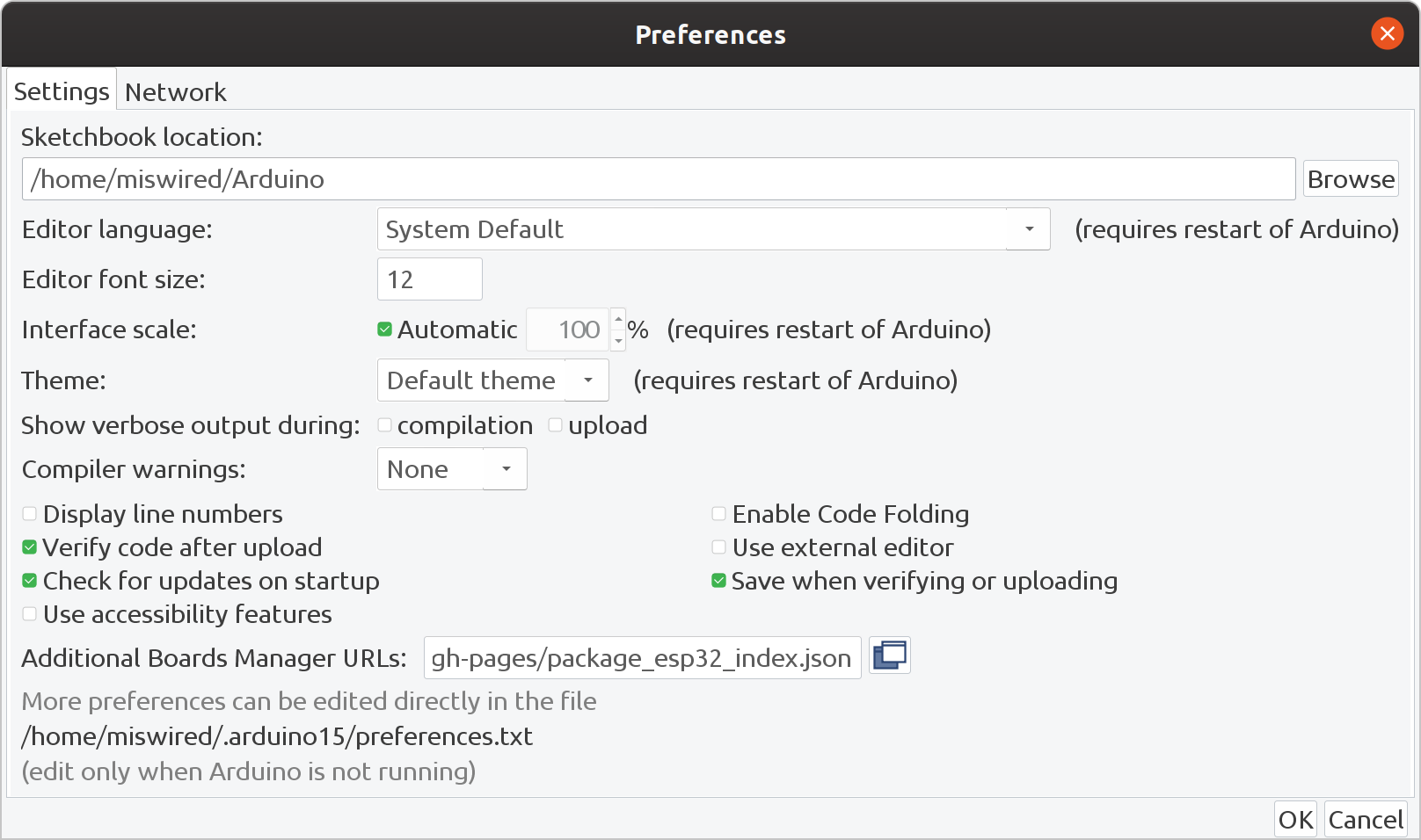
Using the board manager in Arduino, add the esp32 board library:
- File>Prefferences>Aditional Boards manager URL
- Add the following link, if you have multiple links you wan in there, separate them by commas.
https://raw.githubusercontent.com/espressif/arduino-esp32/gh-pages/package_esp32_index.json
Now install the esp32 board support:
- Tools > Board menu
- Search for and install esp32 platform
- Make sure you can select esp32 from Tools>Board
Make sure it’s configured like this:
Board: ESP32 Dev Module
Upload Speed: 921600
CPU Frequency: 240Mhz (WiFi/BT)
Flash Frequency: 80Mhz
Flash Mode: QIO
Flash Size: 4MB (32Mb)
Partition Scheme: Default 4MB with spiffs (1.2MB APP/1.5 SPIFFS)
Core Debug Level: None
PSRAM: Disabled
Port: COM port that appears and disappears when T-Display is connected/disconnected
Adding the TFT_eSPI Library from Bodmer
- Tools > Library Manager, search for TFT_eSPI
- Install it
This is where things got tricky following the official guide. They left out some very important parts at the time of this writing. The website just says:
” Locate and open the file User_Setup_Select.h in a text editor Comment out the line with #include Uncomment the line with #include Load File > Examples > TFT_eSPI > Test and Diagnostics > Colour_Test “
It leaves out the lines and seems to misses that you need to open two files. Here is what I did to get it to work.
- Find your libraries folder. I thought this would be the libraries folder in the extracted directory of the Arduino program, but it turns out that when you add libraries from the manager, it puts it in the arduino folder of the profile. So look in your home directory for Arduino. I was on linux so it was directly in my home directory. I think in windows this is in your My Documents directory.
- You should see something like /Arduino/libraries/TFT-eSPI
- Locate User_Setup_Select.h
- Comment out any include line that isn’t already commented out, then find the following line and uncomment it.
#include <User_Setups/Setup25_TTGO_T_Display.h> // Setup file for ESP32 and TTGO T-Display ST7789V SPI bus TFT
When I was done, my comment section looked like this:
// Only ONE line below should be uncommented.  Add extra lines and files as needed.

#include <User_Setup.h>           // Default setup is root library folder

//#include <User_Setups/Setup1_ILI9341.h>  // Setup file configured for my ILI9341
//#include <User_Setups/Setup2_ST7735.h>   // Setup file configured for my ST7735
//#include <User_Setups/Setup3_ILI9163.h>  // Setup file configured for my ILI9163
//#include <User_Setups/Setup4_S6D02A1.h>  // Setup file configured for my S6D02A1
//#include <User_Setups/Setup5_RPi_ILI9486.h>        // Setup file configured for my stock RPi TFT
//#include <User_Setups/Setup6_RPi_Wr_ILI9486.h>     // Setup file configured for my modified RPi TFT
//#include <User_Setups/Setup7_ST7735_128x128.h>     // Setup file configured for my ST7735 128x128 display
//#include <User_Setups/Setup8_ILI9163_128x128.h>    // Setup file configured for my ILI9163 128x128 display
//#include <User_Setups/Setup9_ST7735_Overlap.h>     // Setup file configured for my ST7735
//#include <User_Setups/Setup10_RPi_touch_ILI9486.h> // Setup file configured for ESP8266 and RPi TFT with touch

//#include <User_Setups/Setup11_RPi_touch_ILI9486.h> // Setup file configured for ESP32 and RPi TFT with touch
//#include <User_Setups/Setup12_M5Stack.h>           // Setup file for the ESP32 based M5Stack
//#include <User_Setups/Setup13_ILI9481_Parallel.h>  // Setup file for the ESP32 with parallel bus TFT
//#include <User_Setups/Setup14_ILI9341_Parallel.h>  // Setup file for the ESP32 with parallel bus TFT
//#include <User_Setups/Setup15_HX8357D.h>           // Setup file configured for HX8357D (untested)
//#include <User_Setups/Setup16_ILI9488_Parallel.h>  // Setup file for the ESP32 with parallel bus TFT
//#include <User_Setups/Setup17_ePaper.h>            // Setup file for any Waveshare ePaper display
//#include <User_Setups/Setup18_ST7789.h>            // Setup file configured for ST7789

//#include <User_Setups/Setup19_RM68140_Parallel.h>	 // Setup file configured for RM68140 with parallel bus

//#include <User_Setups/Setup20_ILI9488.h>           // Setup file for ESP8266 and ILI9488 SPI bus TFT
//#include <User_Setups/Setup21_ILI9488.h>           // Setup file for ESP32 and ILI9488 SPI bus TFT

//#include <User_Setups/Setup22_TTGO_T4.h>           // Setup file for ESP32 and TTGO T4 version 1.2
//#include <User_Setups/Setup22_TTGO_T4_v1.3.h>      // Setup file for ESP32 and TTGO T4 version 1.3
//#include <User_Setups/Setup23_TTGO_TM.h>           // Setup file for ESP32 and TTGO TM ST7789 SPI bus TFT
//#include <User_Setups/Setup24_ST7789.h>            // Setup file configured for ST7789 240 x 240
#include <User_Setups/Setup25_TTGO_T_Display.h>    // Setup file for ESP32 and TTGO T-Display ST7789V SPI bus TFT
//#include <User_Setups/Setup26_TTGO_T_Wristband.h>  // Setup file for ESP32 and TTGO T-Wristband ST7735 SPI bus TFT

//#include <User_Setups/Setup27_RPi_ST7796_ESP32.h>    // ESP32   RPi MHS-4.0 inch Display-B
//#include <User_Setups/Setup28_RPi_ST7796_ESP8266.h>  // ESP8266 RPi MHS-4.0 inch Display-B

//#include <User_Setups/Setup29_ILI9341_STM32.h>          // Setup for Nucleo board
//#include <User_Setups/Setup30_ILI9341_Parallel_STM32.h> // Setup for Nucleo board and parallel display
//#include <User_Setups/Setup31_ST7796_Parallel_STM32.h>  // Setup for Nucleo board and parallel display
//#include <User_Setups/Setup32_ILI9341_STM32F103.h>        // Setup for "Blue Pill"

//#include <User_Setups/Setup33_RPi_ILI9486_STM32.h>      // Setup for Nucleo board

//#include <User_Setups/Setup34_ILI9481_Parallel_STM32.h> // Setup for Nucleo board and parallel display
//#include <User_Setups/Setup35_ILI9341_STM32_Port_Bus.h> // Setup for STM32 port A parallel display

//#include <User_Setups/Setup36_RPi_touch_ILI9341.h>      // Setup file configured for ESP32 and RPi TFT with touch

//#include <User_Setups/Setup43_ST7735.h>            // Setup file configured for my ST7735S 80x160
//#include <User_Setups/Setup44_TTGO_CameraPlus.h>  // Setup file for ESP32 and TTGO T-CameraPlus ST7789 SPI bus TFT    240x240
//#include <User_Setups/Setup45_TTGO_T_Watch.h>     // Setup file for ESP32 and TTGO T-Watch ST7789 SPI bus TFT  240x240

//#include <User_Setups/Setup135_ST7789.h>           // Setup file for ESP8266 and ST7789 135 x 240 TFT

//#include <User_Setups/SetupX_Template.h>


#endif // USER_SETUP_LOADED
- Now you need to make edits in the User_Setup.h file. The original instructions didn’t mention this one but the comments in the library header does. Through a lot of digging and trying to figure out which version of the display this board was using I found the following worked.
- Comment out the other #define lines and uncomment this one:
#define ST7789_DRIVER // Full configuration option, define additional parameters below for this display
When I was done my define section looked like this:
// ##################################################################################
//
// Section 1. Call up the right driver file and any options for it
//
// ##################################################################################

// Define STM32 to invoke optimised processor support (only for STM32)
//#define STM32

// Defining the STM32 board allows the library to optimise the performance
// for UNO compatible "MCUfriend" style shields
//#define NUCLEO_64_TFT
//#define NUCLEO_144_TFT

// STM32 8 bit parallel only:
// If STN32 Port A or B pins 0-7 are used for 8 bit parallel data bus bits 0-7
// then this will improve rendering performance by a factor of ~8x
//#define STM_PORTA_DATA_BUS
//#define STM_PORTA_DATA_BUS

// Tell the library to use 8 bit parallel mode (otherwise SPI is assumed)
//#define TFT_PARALLEL_8_BIT

// Display type -  only define if RPi display
//#define RPI_DISPLAY_TYPE // 20MHz maximum SPI

// Only define one driver, the other ones must be commented out
//#define ILI9341_DRIVER
//#define ST7735_DRIVER      // Define additional parameters below for this display
//#define ILI9163_DRIVER     // Define additional parameters below for this display
//#define S6D02A1_DRIVER
//#define RPI_ILI9486_DRIVER // 20MHz maximum SPI
//#define HX8357D_DRIVER
//#define ILI9481_DRIVER
//#define ILI9486_DRIVER
//#define ILI9488_DRIVER     // WARNING: Do not connect ILI9488 display SDO to MISO if other devices share the SPI bus (TFT SDO does NOT tristate when CS is high)
#define ST7789_DRIVER      // Full configuration option, define additional parameters below for this display
//#define ST7789_2_DRIVER    // Minimal configuration option, define additional parameters below for this display
//#define R61581_DRIVER
//#define RM68140_DRIVER
//#define ST7796_DRIVER

// Some displays support SPI reads via the MISO pin, other displays have a single
// bi-directional SDA pin and the library will try to read this via the MOSI line.
// To use the SDA line for reading data from the TFT uncomment the following line:

// #define TFT_SDA_READ      // This option is for ESP32 ONLY, tested with ST7789 display only

// For ST7789 and ILI9341 ONLY, define the colour order IF the blue and red are swapped on your display
// Try ONE option at a time to find the correct colour order for your display

//  #define TFT_RGB_ORDER TFT_RGB  // Colour order Red-Green-Blue
//  #define TFT_RGB_ORDER TFT_BGR  // Colour order Blue-Green-Red

// For M5Stack ESP32 module with integrated ILI9341 display ONLY, remove // in line below

// #define M5STACK

// For ST7789, ST7735 and ILI9163 ONLY, define the pixel width and height in portrait orientation
// #define TFT_WIDTH  80
// #define TFT_WIDTH  128
// #define TFT_WIDTH  240 // ST7789 240 x 240 and 240 x 320
// #define TFT_HEIGHT 160
// #define TFT_HEIGHT 128
// #define TFT_HEIGHT 240 // ST7789 240 x 240
// #define TFT_HEIGHT 320 // ST7789 240 x 320

// For ST7735 ONLY, define the type of display, originally this was based on the
// colour of the tab on the screen protector film but this is not always true, so try
// out the different options below if the screen does not display graphics correctly,
// e.g. colours wrong, mirror images, or tray pixels at the edges.
// Comment out ALL BUT ONE of these options for a ST7735 display driver, save this
// this User_Setup file, then rebuild and upload the sketch to the board again:

// #define ST7735_INITB
// #define ST7735_GREENTAB
// #define ST7735_GREENTAB2
// #define ST7735_GREENTAB3
// #define ST7735_GREENTAB128    // For 128 x 128 display
// #define ST7735_GREENTAB160x80 // For 160 x 80 display (BGR, inverted, 26 offset)
// #define ST7735_REDTAB
// #define ST7735_BLACKTAB
// #define ST7735_REDTAB160x80   // For 160 x 80 display with 24 pixel offset

// If colours are inverted (white shows as black) then uncomment one of the next
// 2 lines try both options, one of the options should correct the inversion.

// #define TFT_INVERSION_ON
// #define TFT_INVERSION_OFF
Testing the configuration
At this point you can now start to load programs onto the badge and test them. Start by loading the following example sketch.
- File>Examples>TFT_eSPI>Test and Diagnostics>Colour_Test
Upload the sketch and it should cycle through colors. Congratulations! You can compile and upload things to the board and use the screen!
If you haven’t already, you can finish building the badge and soldering the ESP32 board to it.
Then I recommend trying out the button test sketch.
HB0057_Joystick.ino
I have also put some code for the bade up on my GitHub account.
HB0057_DC28_Badge Repo
BetterMario
This project contains a better example of Mario sounds that I ported to the badge. I felt like that Mario example that came from the HackerBox instructable didn’t quite do it for me. See the project for references and credits.
GetMAC
A simple sketch that displays the ESP32’s MAC address. Handy for pairing boards. See project for credits.
Comms
This sketch demonstrates an example of wireless comms between two ESP32 boards using the ESP-NOW library. This is the main sketch that should be put on the HB0057 badge. There is LOTS to improve here, but it does work and maybe someone will find it helpful. ¯_(ツ)_/¯
Comms_Peer
This is a simple sketch that waits for a ping request and responds to the board running the Comms sketch. This can be run on a standalone ESP32 without a screen.